Ground Loop Primer Printer Friendly PDF
One of the most frustrating problems of the measurement and control industry is that of the ground loop. Its effects can appear and disappear with no apparent reason and can range from mere annoyance to downright destructive. It seems that ground loops carry some mystical connotation to the point that our industry has made it a “catch all” culprit for anything that cannot be explained.
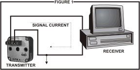
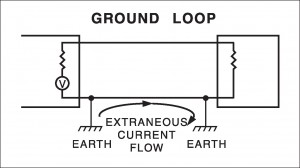
While ground loops can be complex problems and may not always be predictable they can be understood and dealt with if we have a little insight into just what they are and how they can affect a transmitted signal. Let us first refer to Figure 1.
This Figure depicts what we might consider to be a typical measurement loop. It has a transmitter sending a signal to a receiver, some finite distance away, over a pair of wires. One side of the signal current has become grounded via internal circuitry and ultimately is tied to earth ground usually via the instrument case.
As depicted in Figure 1, this measurement loop would probably work fine and not have any influence from ground loop currents. However, reality sets in and we have to abide by plant safety procedures, the National Electric Code, etc. Safety procedures almost always will mandate that each piece of equipment be grounded to earth at its respective installed location. This is where the trouble starts.
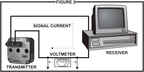
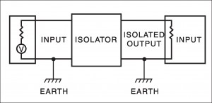
Once we ground two pieces of equipment at two different locations we have set the stage for ground loop problems. If we could take a volt meter (Figure 2) with very long leads and measure the voltage between the ground points of the transmitter and the receiver we would measure some voltage.
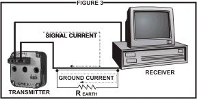
It may measure in millivolts or it could be many volts. Either way, if there is a potential difference, then current will flow between these two points. Since the earth presents itself as a resistor between these two ground points the amount of current that flows between the points will be directly proportional to the voltage difference and inversely proportional to the resistance.
For those who are fans of Ohms Law you will recognize this equated as I=E/R. I being the ground current; E being the voltage between the ground points; and R being the resistance of the earth between the two ground points.
Figure 3 shows that we now have two currents that can flow through the wiring between the transmitter and receiver. If it all stopped here we could just calibrate the measurement loop to nullify the effects of the ground current and go on about our business.
Many times this is exactly what happens. A technician calibrates the loop and comes back a few days later to find that his calibration is no longer accurate. What has happened? It could be a lot of things. Maybe it rained and the resistance of the earth changed. Suffice it to say there are many phenomenons, either natural or man-made, that can change the resistance or the voltage between the two ground points thus effecting the calibration of the loop.
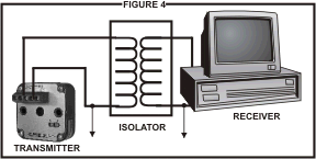
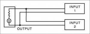
It is apparent that we are “fighting a losing battle” thinking we can anticipate the interactive affect of ground loop currents on our measurement loop. What can we do to get around this problem? The answer is to provide DC isolation between each component in our loop. (Figure 4) DC isolation can be accomplished either in the transmitter, the receiver, or with a third component as shown in Figure 4.
Figure 4 shows DC isolation being accomplished by using a transformer. An isolator module, of course, is much more than just a transformer, but it is the transformer component in a signal isolator that, in fact, provides the isolation since DC cannot pass through a transformer. Now that we have inserted this “transformer” into the circuit, the ground loop between the transmitter and the receiver no longer exists, thus eliminating its effects on the signal current.
The Wilkerson product line provides several options for implementing DC isolation depending on how the isolator is powered. There are three basic ways of powering an isolator.
These are listed below with the respective modules:
1. Input Powered or Loop Powered
2. Output Powered or Two Wire
3. External Powered

