Archive for Thermocouple

How Thermocouples Work Type J

HOW THERMOCOUPLES WORK 

The thermoelectric effect of heated conductors was discovered by a German physicist Thomas Johann Seebeck in 1821. His discovery of any conductor with a thermal gradient would generate a voltage lead to the development of accurate temperature measurement with two dissimilar metal wires now commonly called thermocouples.

Thermocouples are made by connecting two dissimilar metal wires together at one end. The open end of the wires will have a potential difference between them if the open ends and the connected ends are at different temperatures. If the open ends of the wires are held at a constant temperature, the voltage measured between them is proportional to the temperature difference between the open ends and the connected ends. With this arrangement, temperatures can be measured because the voltage created is consistently repeated versus temperature differences if the open ends are held at a reference temperature. The open ends are connected to terminals referred to as the “cold junction terminals”.

In earlier times, zero degrees centigrade was the reference, but modern technology made reference temperatures easier to create. Electronic temperature measurements with thermistors, diodes, and other small electronic devices allowed the temperature of the cold junction terminals to be measured. The voltage the thermocouple creates at this temperature is added to the voltage measured at the cold junction terminals. The results make the signal level the same it would be if the cold junction terminals were at zero degrees centigrade. Zero degrees centigrade is the cold junction reference for the common voltage charts for thermocouples.

The National Institute of Standards and Technology (NIST), a division of the U. S. Department of Commerce, has created voltage charts for common thermocouples. Copies of these charts are available free from most thermocouple manufacturers and can be downloaded as PDF files from the internet.

 J THERMOCOUPLE

The J thermocouple is made of an iron wire (+ positive lead colored white) and a copper-nickel (Constantan) alloy wire (- negative lead colored red). It has a sensitivity of approximately 50 microvolts / deg C and an overall temperature range of -210C to 1200C, but is normally limited to narrower ranges. It has a limited range of -40C to 750C due to the Curie point of the iron at 770C. The iron undergoes a molecular change and permanently loses its standard voltage output versus temperature. It does not recover when the iron is cooled.

It should not be used at high temperatures in an oxidizing atmosphere. A reduction atmosphere is desired. Use at low temperatures is also not recommended

The J thermocouple is one of the lowest cost thermocouples.

The linearity of the J thermocouple varies by -70 degrees C over it full range from -210C to 1200C. It has a very straight section from 100C to 500C which deviates about -0.5C. The lower and higher ranges can be extended with a loss in linearity.


SC5010 Two wire Transmitter

SC5010 Two wire Transmitter With Thermocouple Lookup Tables

Modern microprocessor based signal conditioners remove linearity problems by measuring the input voltage and using this value to check a memory chip to see what temperature it represents. It then creates the correct voltage via a digital to analog converter to make the output linear. It also does the same process if it is sending serial digital data instead of an analog signal. With a digital signal conditioner, the use of the J Thermocouple becomes limited by the environment and temperature range required.

A typical digital 2 wire transmitter has a membrane keyboard for setup. An LCD display is required so the setup process can be observed.

This transmitter will process signals from J,K,R,S,T,E,N thermocouples as well as .00385 and .00392 alpha platinum RTD’s. Linearization is accomplished with 256 point lookup tables stored in chip memory.

Linearity is important only if the absolute temperature measurement is needed over a large temperature spread. If one temperature is required for process control, repeatability of a given temperature is important, but linearity is not required.

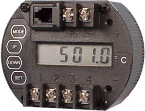
Thermocouple Two Wire Transmitters

THERMOCOUPLE 2 WIRE TRANSMITTERS

THE THERMOCOUPLE

Thermocouples are temperature measuring sensors which are made of 2 dissimilar metals. The metal is typically in the form of wire and the end of one wire is welded to the end of the 2nd wire. If the 2 wires are insulated from each other and run closely parallel to each other, a thermocouple is formed.

A voltmeter placed across the open ends of the parallel wires will indicate a voltage if the welded ends are at a different temperature . If the ends are at the same temperature, zero volts will be observed.

If the open end of the wires are held at a constant temperature, the voltage read by the meter is proportional to the temperature difference between the ends of the thermocouple.

The sensitivity of the thermocouple is determined by the two metals used in its construction.

Since the beginning of thermocouple technology, different metals have been used to make thermocouples for use in different applications and environments.

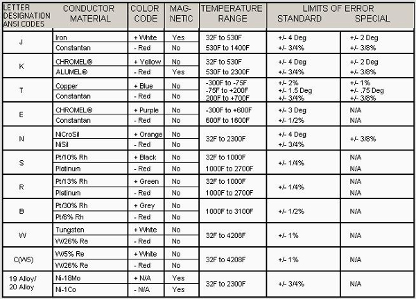
Thermocouples have their leads color coded for identification. Some have magnetic leads so they can be identified with a magnet. (see chart at end)

SIGNAL LEVELS

Thermocouples create very low signals. The J thermocouple creates about 52 microvolts per degree centigrade difference in temperature. The B thermocouple creates about 4.8 microvolts.

COLD JUNCTION COMPENSATION

2 wire transmitters for thermocouples have 2 difficult requirements to meet. The signal levels are very low and temperature stability of the circuits is a challenge.

The 2nd requirement is the 2 leads of the thermocouple connected to the transmitter terminals must be held at the same temperature. Any difference in temperature at the transmitter end changes the signal by this amount.

The transmitter terminals are referred to as the cold junction compensation connection.

A typical method of controlling the transmitter end temperature is to connect the 2 wires to 2 large masses of metal which are insulated from each other. They are thermally bonded together so they maintain the same temperatures for the thermocouple leads. A small temperature sensor is embedded in the metal mass and the temperature of the mass is measured accurately. This temperature is added to the signal from the thermocouple.

Thermocouple voltage charts are referred to the temperature of the junction end with the cold junction end being at 0°C.

LINEARITY AND STABILITY

No thermocouple is linear over a wide temperature range. When the temperature must be known accurately, linearity and stability is required.

Many applications, such as alarms, only require accuracy in repeatability.

Accurate linearity requires a microprocessor based transmitter. With this design, a lookup table of temperature vs signal level can be used for accuracy. A single transmitter can carry lookup tables for many thermocouple types. With this asset, a single transmitter can serve in many applications.

The microprocessor based transmitter can also reduce drift by checking the gain and offset of the signal amplifiers against a precision reference voltage and zero offset (ground). It performs a math equation every sample to remove amplifier gain drift and offset drift.

This capability of auto zero makes the transmitter as accurate and stable as the reference voltage used for comparison.

GROUND LOOPS AND SIGNAL NOISE

Due to the low levels of signals thermocouples create, the system of thermocouple and 2 Wire transmitter requires care in wiring to prevent noise pickup.

Many thermocouple probes have the thermocouple wire welded to the end of the metal sheath which houses the thermocouple wire. Connecting the wire to the metal tube allows a faster response to temperature changes.

If the metal sheath is grounded to the earth through the pipe or other metal object it is mounted to, it makes a safer installation. Lightning in an area can create powerful magnetic fields which can create sparks from ungrounded metal object to grounded objects.

Welding the thermocouple wire to a grounded sheath prevents sparks from leaving the thermocouple wire to a grounded object. Such a spark could be devastating in the wrong environment.

The grounded thermocouple wire creates an opportunity for a ground loop if an electrical path exists from the thermocouple to another ground connection in the system.

Due to the common practice of grounded thermocouples, it is wise to use isolated 2 wire transmitters to prevent ground loops.

Thermocouple wires should not be run in the same cable trough or conduit as AC power wiring.

Capacitive or magnetic coupling will induce an AC current in the thermocouple wire and the signal will have AC “noise” imposed on the DC signal.

SOME TYPICAL THERMOCOUPLES

Thermocouple probe with head to hold 2 Wire Transmitter. Probe mounts on pipe fitting with probe protruding into pipe or tank.

Thermocouple Probe with Explosion Head

Thermocouple probe for mounting on pipe fitting with probe located at point of measurement. Connector on wire to plug into measuring instrument.

Thermocouple Probe Pipe Fitting Mount

Ceramic beaded thermocouple for high temperature measurement. Leads connect to extension wire or instrument.

Ceramic Beaded Thermocouple Probe

CHART OF COMMON THERMOCOUPLES


Common Thermocouple Chart

Common Thermocouple Chart

ANSI – AMERICAN NATIONAL STANDARDS INSTITUTE

© Joe E. Wilkerson 2012

Follow

Get every new post on this blog delivered to your Inbox.

Join other followers: