TWO WIRE TRANSMITTERS A POWERFUL TOOL
Two wire transmitters are one of the most used electronic instruments in the process industries.
Their flexibility and accuracy of measurements makes them the instrument of choice in many applications.
How They Work
A two wire transmitter is an electronic circuit which is designed to run on less than 4mA of current.
A Zero adjustment makes the circuit draw exactly 4.00mA when the measured signal is at its Zero Scale level.
The circuit will make the current rise to exactly 20.00mA when the measured signal rises to its Full Scale level.
The current drawn from the power supply is constant and is not dependent on the power supply voltage. This feature allows the desired signal to be read anywhere the power supply wire lead can be opened and a small resistor put in series with the lead. The voltage drop across the resistor is an accurate indication of the measured signal.
The constant current can drive total load resistors until the voltage dropped by the loads equals the saturation voltage of the Transmitter output circuit. The compliance of the Transmitter is determined by the design of the circuits.
The universal standard of having the current go from 4.00mA to 20.00mA allows the two wire TX to be used anywhere in the world. A multitude of products exist which accept the 4.00mA to 20.00mA signal as an input signal.
One of the two major advantages of the 2 wire TX is the distance from the sensor to the signal conditioning circuit can be extremely short. This is a great advantage for thermocouple measurements. Often, the 2 wire TX is mounted on the TC sensor and no extra thermocouple wire is needed.
RTD sensors can often be 2 leads instead of 3 or 4 leads, because the 2 wire TX can be mounted on the sensor.
Where small signal levels are encountered, such as strain gauges, short wiring from the sensor to the 2 wire TX helps keep noise off the signal leads.
The other great advantage is the power supply leads for the 2 wire TX can be 1000’s of feet long and the lead can be opened anywhere so the signal can be read. Also since the signal is a constant current, the resistance of the power supply leads does not affect the output signal level.
Loop Powered Displays exist which can indicate the current in the wiring loop. The displays require very little current to operate. They usually have adjustments so the indication can be in the desired engineering units instead of just mA.
Modern technology has made 2 wire transmitters easier to design. Amplifiers are available which require only 10 microamps of current to fuction. These allow some complex circuits to be developed and function on less than 4mA. It expands the range of 2 wire TX’s which can be developed.
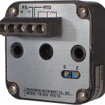
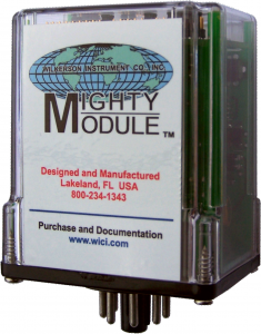
Wilkerson Instrument offers the following two wire instrumentation products
The SR Series Two Wire Transmitters offer inputs for DC , RTD, Thermocouple, Frequency, and Potentiometer Position
in a 50 mm Case size for DIN connection heads, flat panel or DIN rail mounting. Plug In range cards offer the ability to change ranges in the field. Some models offer galvanic input to output isolation.
The TW SeriesTwo Wire Transmitters offer an economic solution for applications requiring low cost transmitters for Potentiometer, RTD, Thermocouple, and Frequency inputs.
The SC Series Two Wire Transmitters feature universal temperature sensor inputs programmable via an onboard keypad or by remote RS232 interface. Linearization for thermocouple types J,K,T,R,S,E, and N is provided as well as inputs for 2, 3 and 4 wire Platinum RTDs.
The SC5010 Two Wire Transmitter also features a 4 1/2 digit digital display and galvanic input to output isolation.
Solutions provider for signal conditioning and process control instrumentation – Wilkerson Instrument Company Inc


