THERMOCOUPLE 2 WIRE TRANSMITTERS
THE THERMOCOUPLE
Thermocouples are temperature measuring sensors which are made of 2 dissimilar metals. The metal is typically in the form of wire and the end of one wire is welded to the end of the 2nd wire. If the 2 wires are insulated from each other and run closely parallel to each other, a thermocouple is formed.
A voltmeter placed across the open ends of the parallel wires will indicate a voltage if the welded ends are at a different temperature . If the ends are at the same temperature, zero volts will be observed.
If the open end of the wires are held at a constant temperature, the voltage read by the meter is proportional to the temperature difference between the ends of the thermocouple.
The sensitivity of the thermocouple is determined by the two metals used in its construction.
Since the beginning of thermocouple technology, different metals have been used to make thermocouples for use in different applications and environments.
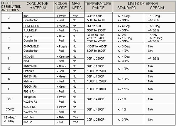
Thermocouples have their leads color coded for identification. Some have magnetic leads so they can be identified with a magnet. (see chart at end)
SIGNAL LEVELS
Thermocouples create very low signals. The J thermocouple creates about 52 microvolts per degree centigrade difference in temperature. The B thermocouple creates about 4.8 microvolts.
COLD JUNCTION COMPENSATION
2 wire transmitters for thermocouples have 2 difficult requirements to meet. The signal levels are very low and temperature stability of the circuits is a challenge.
The 2nd requirement is the 2 leads of the thermocouple connected to the transmitter terminals must be held at the same temperature. Any difference in temperature at the transmitter end changes the signal by this amount.
The transmitter terminals are referred to as the cold junction compensation connection.
A typical method of controlling the transmitter end temperature is to connect the 2 wires to 2 large masses of metal which are insulated from each other. They are thermally bonded together so they maintain the same temperatures for the thermocouple leads. A small temperature sensor is embedded in the metal mass and the temperature of the mass is measured accurately. This temperature is added to the signal from the thermocouple.
Thermocouple voltage charts are referred to the temperature of the junction end with the cold junction end being at 0°C.
LINEARITY AND STABILITY
No thermocouple is linear over a wide temperature range. When the temperature must be known accurately, linearity and stability is required.
Many applications, such as alarms, only require accuracy in repeatability.
Accurate linearity requires a microprocessor based transmitter. With this design, a lookup table of temperature vs signal level can be used for accuracy. A single transmitter can carry lookup tables for many thermocouple types. With this asset, a single transmitter can serve in many applications.
The microprocessor based transmitter can also reduce drift by checking the gain and offset of the signal amplifiers against a precision reference voltage and zero offset (ground). It performs a math equation every sample to remove amplifier gain drift and offset drift.
This capability of auto zero makes the transmitter as accurate and stable as the reference voltage used for comparison.
GROUND LOOPS AND SIGNAL NOISE
Due to the low levels of signals thermocouples create, the system of thermocouple and 2 Wire transmitter requires care in wiring to prevent noise pickup.
Many thermocouple probes have the thermocouple wire welded to the end of the metal sheath which houses the thermocouple wire. Connecting the wire to the metal tube allows a faster response to temperature changes.
If the metal sheath is grounded to the earth through the pipe or other metal object it is mounted to, it makes a safer installation. Lightning in an area can create powerful magnetic fields which can create sparks from ungrounded metal object to grounded objects.
Welding the thermocouple wire to a grounded sheath prevents sparks from leaving the thermocouple wire to a grounded object. Such a spark could be devastating in the wrong environment.
The grounded thermocouple wire creates an opportunity for a ground loop if an electrical path exists from the thermocouple to another ground connection in the system.
Due to the common practice of grounded thermocouples, it is wise to use isolated 2 wire transmitters to prevent ground loops.
Thermocouple wires should not be run in the same cable trough or conduit as AC power wiring.
Capacitive or magnetic coupling will induce an AC current in the thermocouple wire and the signal will have AC “noise” imposed on the DC signal.
SOME TYPICAL THERMOCOUPLES
Thermocouple probe with head to hold 2 Wire Transmitter. Probe mounts on pipe fitting with probe protruding into pipe or tank.

Thermocouple probe for mounting on pipe fitting with probe located at point of measurement. Connector on wire to plug into measuring instrument.

Ceramic beaded thermocouple for high temperature measurement. Leads connect to extension wire or instrument.

CHART OF COMMON THERMOCOUPLES

Common Thermocouple Chart
ANSI – AMERICAN NATIONAL STANDARDS INSTITUTE
© Joe E. Wilkerson 2012


