Wireless Control of Life Support System in an Exotic Aquarium for Show Animals
APPLICATION
Park engineers have an application sending a 4/20mA signal from an ORP (Oxidation Reduction Potential) sensor to a Control Room approximately 500 feet away.
The ORP sensor is used to electronically monitor the amounts of sanitizer and other chemicals in the water, before it enters the large holding tank.
Rain or shine, a ladder is climbed to the top of a pump house building several times everyday to take readings. This posed a safety and health risk to the operator as well as only provided sporadic measurement cycles.
The EPA requires monitoring of this chemical system for both human and animal safety.
More Info: Frequency Hopping Spread Spectrum Technology
More Info: Value of Isolated Signal Conditioners
USER REQUIREMENTS
The ORP monitor where the reading was taken is in a hard to reach location at the top of a pump house on the side of the tank.
Due to a large amount of sidewalks and other obstacles, it was not cost effective to run wires from the sensors to the Control Room.
WIRELESS POSSIBILITY
Checking the 500 foot line of sight between the Transmitter and Receiver locations indicated there was a 50 foot elevation difference. The check of the antenna path also indicated there was a large building near the Receiver. There are also several trees in the antenna path.
More Info: How to calculate your antenna needs
WILKERSON INSTRUMENT’ SOLUTION
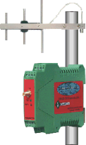
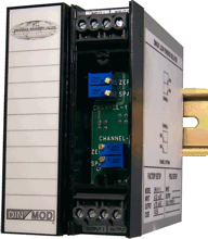
Use a 900 MHz Band Transmitter (DR9011, 2 analog and 4 switch inputs) at the top of the building to monitor the 4/20mA signal from the ORP sensor.
The DR9011 was installed inside a NEMA 4X housing. A small 3” high 2.1dBi gain vertical antenna was mounted on the top of the NEMA 4X housing.
Use a 900 MHz Band Receiver (DR9021, 2 analog and 4 switch outputs) at the LSS Control to receive the data coming from the DR9011 Transmitter.
This unit was installed inside a pre-existing control panel. Along with a wall mount 3 element directional Yagi antenna (8dBi gain) to the top of the LSS (Life Support System) Control building.
The use of the Omni directional antenna at the sensor end allowed the signal to be transmitted across a wider path. In using the Yagi antenna at the receiver side, the install crew was able to choose the best location and path for pointing the Yagi antenna.
The trees and building posed difficulty by either blocking part of or potentially causing a reflected signal in the Fersnel Zone. The Yagi helped eliminate this due to its narrow beam width.
This system has been reliably sending data since June 2007.


