Differential Pressure Measurement Across Liquid Filters in a Beverage Processing Plant

DIFFERENTIAL PRESSURE MEASUREMENT ACROSS LIQUID FILTERS IN A BEVERAGE PROCESSING PLANT

SYSTEM REQUIREMENT:

Measure the pressure drop across each filter in a bank of filters to determine when to switch to a fresh filter(s) so the clogged one(s) can be cleaned.

Provide electrical isolation between each input signal as well as between input to output to prevent noise pickup and noise from ground loops.

Wilkerson  Instrument Co. Products Used


Mighty Module Wilkerson Instrument

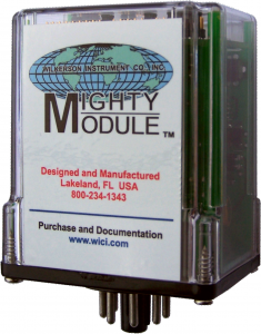
Mighty Module


Mighty Module Wilkerson Instrument

Mighty Module


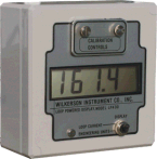
LP400 Loop Power Display

MM4408 MM4300 LP4OO
TWO-INPUT ISOLATED DC DIFFERENCE TRANSMITTER (OUTPUT = A – B) ISOLATED SIGNAL CONDITIONER LOOP POWERED DISPLAY
Specification PDF Specification PDF Specification PDF
I/O Manual PDF I/O Manual PDF I/O Manual PDF
How To Order How To Order How To Order


SYSTEM SYNOPSIS

Many beverage processing plants utilize filters at various stages of the process to remove unwanted materials from the liquid. As these filters load up doing their job, the flow passing through the filter is reduced. If the filters are not replaced or cleaned, the flow can be impeded enough to disrupt the total process.

This particular application surfaced when the customer was faced with replacing an old pneumatic system. The customer wanted to install an electronic system using strictly “off-the-shelf” commercially available equipment. He was faced with very limited control panel space and limited budget. Therefore, the system must use the fewest components possible and the smallest displays available.

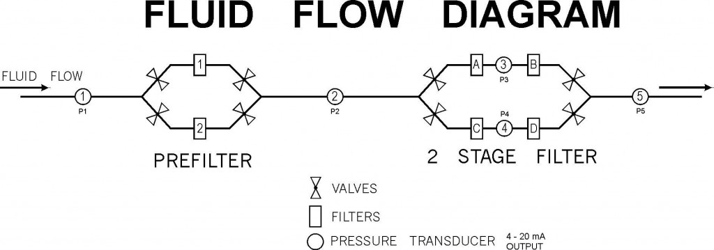
The Fluid Flow Diagram shows the basic arrangement of the pressure transducers and the filters. Only one prefilter and one two-stage filter are in service at any given time.


Fluid Flow Diagram - Bottling Plant

Fluid Flow Diagram - Bottling Plant


This allows the other filter(s) to be cleaned, sterilized and made ready for service.

USDA approved pressure transducers that are cleaned and sterilized in place were selected. By placing transducers 1, 2 and 5 so their use is common to either prefilter and either filter bank in use, the customer needed only five pressure transducers to do the job.

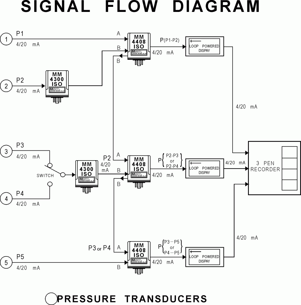
The Signal Flow Diagram shows how the customer’s judicious use of a switch, two MM4300 DC to DC transmitters, and three MM4408 difference transmitters achieves the needed input to input and input to output signal isolation with only five modules.

Signal Flow Diagram

Signal Flow Diagram

SOLUTION

The product chosen to measure the differential pressure (pressure drop) across the filter was the MM4408 and the MM4300.

The MM4408 inputs are not isolated from each other, but the output is isolated from both inputs.

The MM4300 signal conditioner has isolation from the input to output.  It is used to provide one input to the MM4408. This provides isolation for both inputs.

Three LP400 loop powered displays in series with the three 4/20mA outputs provides an indication of the pressure on the output of the filters.  The Display can be calibrated in engineering units to fit the need.

Wilkerson Instrument Company Inc Is a solutions provider for signal conditioning and process control instrumentation  –   Copyright 2012


Automatic Temperature Control In a Sugar Refinery

AUTOMATIC TEMPERATURE CONTROL IN A SUGAR REFINERY

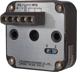
TW303 LOW-COST RTD TWO-WIRE TRANSMITTER

TW303 Two-Wire Transmitter

TW303 - Specifications and I/O manual

FEATURES:

  • Provides 4/20 mAdc current output  proportional to an RTD input
  • Any 2-wire or 3-wire RTD  (100 ohms to 2000 ohms)
  • Linearized for platinum RTD
  • Any input range within RTD limit  (50°F minimum span)
  • Low-drift chopper-stabilized input
  • Operating temperature range -13°F to 176°F
  • Temperature stability of ±0.02% of span per °C
  • Operates on 12 V to 48 VDC
  • Conformal coated to resist corrosion,  moisture and fungus
  • Low cost
  • Small size – 50mm X 50mm
  • Our standard 5 year warranty

PROBLEM:                              Specification Sheet PDF      I/O Manual PDF

To replace manually read thermometers with 3-wire, 100 ohm, platinum RTDs allowing all temperature readings to be taken in a central control room. Also, to provide automatic temperature control for more efficient control of the refining process.

INTRODUCTION:

Historically, sugar refineries are reluctant to spend money on capital equipment. As a result, they tend to be slow in automating their process. Many still utilize manual thermometers that require some-one to “make the rounds” to read the temperatures and make manual adjustments to the steam valves.

This process is cumbersome and slow, particularly when trying to maintain constant temperature at multiple sites. Those refineries who have made the plunge have found that automation of the process has among other things, greatly improved the efficiency of the process.

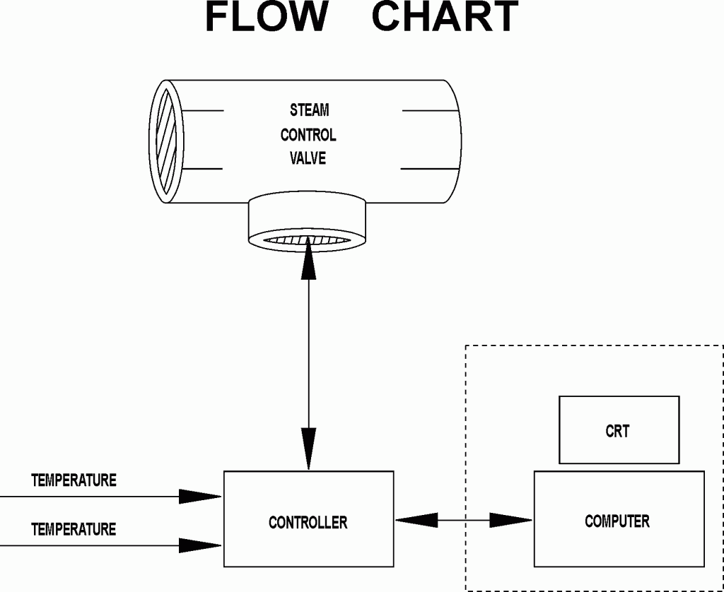
In this particular application, shown in the flow chart, the customer must read and maintain temperatures at multiple locations including in/out temperatures of heat exchangers as well as the top/bottom temperatures in the pan. The pan temperatures must be exactly right in order to “seed” them to make crystal.


Steam Flow Chart - Temperature Control In a Sugar Refinery - TW303 - Wilkerson Instrument

Flow Chart

The customer chose to automate the plant with Moore 352E programmable loop controllers to control each temperature control loop, Fisher Controls steam valves and a central computer to poll each controller for CRT readout and data gathering in the control room.

Each Moore 352E can handle up to 5 analog inputs and 3 analog outputs. In addition, the 352E has a resident 24 V power supply capable of powering up to at least 3 current loops. However, in order to read an RTD directly, the 352E must be equipped with an optional RTD input at a cost of about $300 each. By using a low cost 2-wire transmitter, the customer can save ap-proximately $200 per RTD input.

SOLUTION:

The product chosen was the TW303 RTD input 2-wire transmitter. Its small size, low cost, reliability, and versatility in mounting (field or panel mount in a variety of industrial housings and enclosures) made it the ideal choice. The transmitter accepts any 2-wire or 3-wire RTD input and has a minimum span of 50°F. It can be calibrated to cover any range desired within the limits of the RTD selected. The module operates over a temperature range from -13°F to 176°F while providing a temperature stability of ±0.02% of span. It will also operate over a supply voltage range of 12 to 48 VDC.

The transmitter design provides accurate trouble-free operation. A single constant current source excites the RTD, but the low excitation current causes no appreciable self-heating in the RTD. An accurate and stable leadwire compensation circuit uses the third lead of the 3-wire RTD to compensate for the RTD lead resistance. Platinum RTD inputs are linearized and use of low-drift chopper-stabilized amplifiers and special filtering reduces susceptibility to transients and noisy operations. In addition, the electronic board and components are conformal coated to resist corrosion, moisture and fungus associated with harsh industrial environments.

These features, a generous 5 year warranty, customer service second to none in the industry, low cost and a recommendation from the Wilkerson representative, led the customer to choose the TW303.

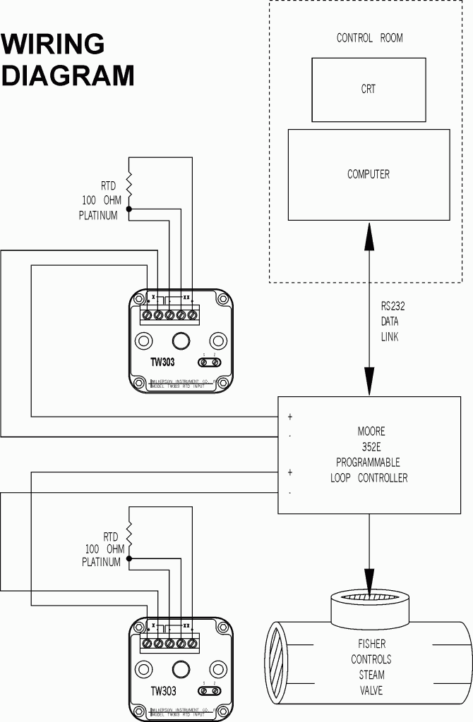
The customer connected them as shown in the wiring diagram.

Wiring Diagram - Temperature Control In a Sugar Refinery - TW303 - Wilkerson Instrument

Wiring Diagram

COST SAVINGS:

Approximately $200 per RTD input.

**********

Copyright Wilkerson Instrument Company Inc. – USA – 2012

http://www.wici.com

http://www.wici.com/blogs/2012/02/automatic-temperature-control-in-a-sugar-refinery/


Follow

Get every new post on this blog delivered to your Inbox.

Join other followers: