DC INPUT ISOLATED TWO WIRE TRANSMITTER AND HOW THEY WORK
An isolated DC input two wire transmitter is a valuable tool for many difficult measurements. The device can measure DC voltage or current inputs and provide a 4mA to 20mA output without a galvanic electrical connection between the input and output.
The isolation between input and output is typically rated with an insulation capability of 1000 volts or more.
HOW THEY WORK – ANALOG CIRCUITS
The transmitter has a DC amplifier as an input circuit. It can typically be calibrated for a current or voltage input. The power for this circuit requires an isolated power supply which uses a transformer for the isolation.
The signal out of this amplifier must be changed to a form which can be sent through the signal isolation circuit.
A common isolation circuit is to convert the DC signal to a square wave AC signal and transformer couple it to the output circuit. The output circuit must convert the square wave AC signal back to a DC voltage which can drive the current output circuit.
Another common circuit is to convert the DC signal to a pulse signal where the data is determined by the width of the pulse. This pulse is passed through an optical isolator and then converted back to a DC signal which drives the current output circuit.
HOW THEY WORK – DIGITAL CIRCUITS
The digital transmitter has a DC amplifier as an input circuit. The power for this circuit requires an isolated power supply which uses a transformer for the isolation.
The level of the DC output is measured with an analog to digital converter. The binary code, in the form of pulses, is passed on to a digital to analog converter through optical isolators. The analog output of the D/A converter drives the current output circuit of the transmitter.
APPLICATIONS FOR ISOLATED DC INPUT 2 WIRE TRANSMITTERS
Common Mode Definition
A DC input transmitter has 2 connections for the input signal. These are the signal input and the common connection. The common connection is the circuit common of the input amplifier.
If the input terminal and the common terminal are connected together, and a signal is connected to this connection, and the other signal lead is connected to its normal place, the transmitter has a common mode input. The signal input and common terminal, being tied together, both have exactly the same signal attached.
The transmitter will not respond to this common mode signal. It only responds to a difference in the level between the signal and common lead.
Application For Common Mode Capability
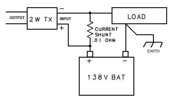
Measure current from a 138V battery pack by putting a .01 ohm resistor in series with the positive lead. Connect the 2W transmitter input across the resistor.
The resistor drops 10mV per amp, which is processed by the transmitter and converted to the constant current output.
The common mode capability of the transmitter allows the signal input leads to be 138VDC above ground, but it can accurately process the low voltage across the shunt resistor.
The current output is not effected by the 138VDC battery voltage.
Application For PLC Input
Some PLC’s provide 24VDC at the input terminals of their analog inputs. A 2 wire transmitter can be connected to the 24VDC. The PLC will monitor the current drawn from the power supply and thereby ascertain the signal level at the remote 2W transmitter.
An isolated DC voltage or DC current 2W transmitter connected to the PLC allows many types of signals to be monitored in the field. The isolation prohibits ground loops and maintains noise free signals into the PLC.


