Value of Isolated 4ma to 20ma Signal Conditioners
DC signal conditioners with 4mA to 20mA outputs provide the ability to send signals over long wires to more than one instrument. The current from the signal conditioner is a constant current proportional to the signal into the signal conditioner. The constant current allows long leads. The level of the measured signal is proportional to the voltage drop across the resistor in the input of the instrument receiving the signal. Voltage drops across the long wires have no effect on the constant current. The constant current allows several instruments to have their inputs wired in series and the current through each input is identical.
Isolated Signal Conditioners provide a further important value. The isolation circuit has no direct electrical connection between the input and output circuits. The input signal is passed through a transformer as an AC signal or through an optical isolator as a light beam.
These two types of circuits make the signal conditioner able to have a high voltage common mode signal while still processing a very low level signal from a sensor or other instrument.
The isolation from input to output also keeps extraneous currents from odd sources from flowing on the common signal lead through the signal conditioner. This extraneous current is usually called a “ground loop”. The isolation breaks this ground loop.
Prevent Ground Loops
A typical ground loop is created when a thermocouple has its welded junction grounded to earth through its mounting hardware. The thermocouple signal is very low in amplitude. If the thermocouple wire has a completed circuit from the thermocouple mount to the earth at the signal conditioner and a current flows in the thermocouple wire, it will impose a voltage on the thermocouple signal. The typical ground loop noise is caused by AC current flowing in the wire. With an isolated signal conditioner, there is no path for current to flow to earth at the conditioner. The isolator breaks the ground loop. The thermocouple signal is amplified and passed on through the isolation circuit to the conditioner output with no noise from the ground loop.
Process Small Signals On High Common Mode Signals
A common mode signal is a signal which is connected to both inputs of a signal conditioner and the conditioner has an output equal to a zero input. An example would be a thermocouple welded to the positive terminal of a 138V battery so the temperature of the battery terminal can be ascertained. The conditioner processes the thermocouple voltage but is not affected by the 138VDC common mode voltage from the battery.
Another example would be a battery with a resistor in series with the + terminal. A signal conditioner can measure the voltage drop across the resistor so the current through the resistor can be determined. The measurement is unaffected by the battery 138V common mode voltage.
A great value of isolated signal conditioners is that common mode ranges of 1000V to 2000V are not difficult to find.
Split One Signal into Many Separated Individually Isolated Signals
A common requirement of 4mA to 20mA outputs from DC input isolated signal conditioners is a need to measure 1 sensor and send the signal to a number of locations in the 4mA to 20mA form.
One method of creating several isolated signals is to connect the inputs of several 4mA to 20mA input/output signal conditioners in series. Each conditioner will provide an isolated output.
Multiple output conditioners are available. If dual output conditioners are used as above, one gets 2 outputs per each input.
Another method is to use one 4ma to 20mA input conditioner. Using voltage input conditioners with 4mA to 20mA outputs, connect the voltage inputs in parallel across the input of the current input conditioner. 250 ohm loads are common inputs for current inputs. This creates 1 to 5V drop across the 250 ohm resistor.
Isolator Creates a Separately Isolated Signal From An Existing Signal With No 2nd Power Supply Required
In areas where power is lacking and another isolated signal is required, a loop powered isolator can do the job. A loop powered isolator uses the 4mA to 20mA current from a signal conditioner to power another circuit to create another isolated output.
 |
 |
 |
 |
 |
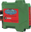
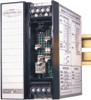
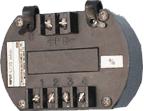
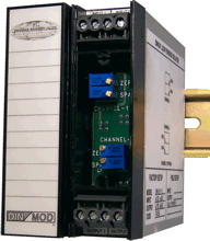
| DR Series | DIN-Mod (DM) |
SR Series | TW8 Series |


